![Forney_FV_logo_signature_600.jpg]](https://knowledge.forneyonline.com/hs-fs/hubfs/Forney_FV_logo_signature_600.jpg?height=40&name=Forney_FV_logo_signature_600.jpg)
Table of Contents
1. Prepare the beam and support span
2. Install the third-point loading fixture
3. Install the deflection cage and both LVDTs
4. Connect and verify the ForneyLink displacement channels
5. Confirm the test-rate program
6. Tare and run the C1609 test
Before you begin
- Use a Forney servo-controlled machine configured and commissioned for ASTM C1609. Forney M models provide Modulus of Elasticity (MOE) capability; MP models provide both MOE and Poisson’s Ratio capability. The M or MP designation alone does not establish that the C1609 option has been enabled.
- Confirm the correct third-point loading attachment is installed. Forney identifies TA-0166-12 as the C1609 flexural accessory and TA-0166-21 as the beam transducer jig; confirm compatibility with your exact machine and fixture drawings.
- Confirm two calibrated LVDT inputs, a valid load calibration, approved machine settings and appropriate guarding. Only trained operators should perform the test.
- Have your specimen dimensions, support span, and ForneyVault Project, Location, Sample and Test set ready. The available ForneyLink options depend on the machine software and the specimen/test configurations in ForneyVault.
Important: This article is an operator workflow, not a replacement for the current ASTM C1609/C1609M standard or the applicable Forney machine and accessory manuals. Do not copy sensor calibration values, preload settings, or controller/VFD tuning from another machine.
1. Prepare the beam and support span
1. Confirm the intended beam size. Use the specimen dimensions permitted by your applicable ASTM method and project requirements. Common arrangements include 4 × 4 × 14 in. and 6 × 6 × 20 in. beams.
2. Set the lower roller span. Use 12 in. for a 4 × 4 × 14 in. beam or 18 in. for a 6 × 6 × 20 in. beam. Check the actual support span before testing.
3. Mark the supports, third points and midspan. The two upper load points must fall at one-third and two-thirds of the support span. Prepare and orient the specimen according to the current method.
|
Typical beam (W × D × length) |
Support span (L) |
L/900 transition |
L/150 target |
|
4 × 4 × 14 in. |
12 in. |
0.0133 in. |
0.080 in. |
|
6 × 6 × 20 in. |
18 in. |
0.0200 in. |
0.120 in. |
Note: Deflection targets depend on span (L). Use the correct specimen profile. The project and current ASTM standard may require other reported deflection points, including L/600.
2. Install the third-point loading fixture
1. Prepare the machine. Follow the machine maintenance/safe-access instructions. Keep the ram in a safe position and remove conflicting fixtures or platens as required by your machine model.
2. Install the upper loading head. Mount and secure the head using the hardware and attachment point shown in the Forney assembly drawing.
3. Position the lower support assembly. Center it on the machine using the specified centering pin, dowels or other model-specific hardware.
4. Set the lower supports and upper loading points. Verify the lower span and third-point spacing, then ensure both assemblies align vertically.
5. Perform the final mechanical check. Confirm free roller rotation, secure mounting and sufficient clearance for the beam cage and LVDT cables.
Machine-specific tip: Forney’s TA-0166 installation article describes lower-platen removal on certain F-250 and F-325 configurations. Follow the drawing for the machine in front of you; do not assume all frames mount identically.
3. Install the deflection cage and both LVDTs
1. Position the cage around the beam. Fit the beam-mounted jig so its reference points are clamped to the specimen directly above the supports, approximately at mid-depth, according to the jig drawing.
2. Install the midspan measuring brackets. Place the strike plates on opposite sides of the beam where the LVDT tips will contact them.
3. Install LVDT 1 and LVDT 2. Place one sensor at midspan on each side. Each sensor tip must contact its plate without side-loading, dragging or slipping.
4. Verify usable sensor travel. Each transducer must have enough remaining stroke to measure the required full deflection. For an 18 in. span, this includes at least the 0.120 in. target, plus appropriate setup allowance.
5. Route cables and check clearances. Keep cables clear of rollers, upper noses, moving frame components and potential beam fragments.
Why the cage matters: The cage measures net beam deflection relative to the supports. Hydraulic ram movement is not a substitute because frame movement, seating and specimen rotation can distort the reading.
4. Connect and verify the ForneyLink displacement channels
Both beam-side LVDTs must be active and scaled correctly. The machine controls the test using the average of the two measurements.
|
ForneyLink channel / setting |
What it represents |
|
Channel 1 |
LVDT measuring net deflection on one side of the beam |
|
Channel 2 |
LVDT measuring net deflection on the opposite side |
|
Ram Position → Average 1 & 2 |
Use the average of both displacement channels for the control feedback |
1. Open Machine Setup. On the applicable ForneyLink, find the Ram Position setting.
2. Select Average 1 & 2. Verify the selection is saved. Choosing only Channel 1 ignores the second LVDT.
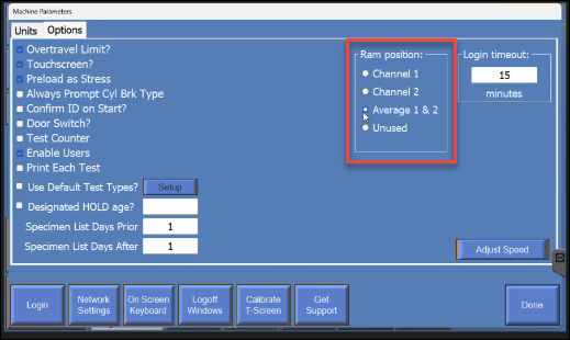
3. Check each live channel before loading. Both signals should respond smoothly and in the expected direction. Confirm sensor scaling and zero position using the approved machine procedure.
4. Stop if the signals disagree significantly. Inspect cable connections, sensor contact, bracket movement, direction and available travel. Obtain Forney support for wiring assignments or calibration constants rather than guessing.
5. Confirm the test-rate program
ASTM C1609 requires slow, closed-loop net-deflection control before and after cracking. The correct program must be configured and verified for the beam size and standard in use.
|
Typical beam |
Initial deflection-rate range |
Subsequent rate range* |
|
4 × 4 × 14 in. |
0.001–0.003 in./min |
0.002–0.008 in./min |
|
6 × 6 × 20 in. |
0.0015–0.004 in./min |
0.002–0.012 in./min |
*Illustrative secondary-source ranges. The permitted changes in rate after L/900 and limits on the rate increases must follow the edition of ASTM C1609 in use. Do not simply jump to the upper rate shown.
6. Tare and run the C1609 test
1. Perform the final fixture check. Confirm correct roller spacing, beam centering, cage attachment, two LVDT contacts, sensor travel and safe cable routing.
2. Verify both displacement signals and tare. Select the Position Value on the ForneyLink screen to zero the load and both beam-deflection channels with the apparatus properly settled.
3. Advance to specimen contact. Use only the normal ForneyLink's Jog Advance controls and the approved preload sequence. Keep hands away from the fixture while energized.
4. Select Start Test. Allow the programmed C1609 profile to regulate the net-deflection rate. Do not substitute a manual ram-speed or strength-control procedure.
5. Observe the live trace. Watch the load-versus-net-deflection curve through first cracking and the post-crack response; both LVDTs must remain engaged.
6. Finish at the programmed endpoint. Stop/abort under your lab’s safety procedure if the cage shifts, either sensor loses contact, travel is exhausted or the system oscillates dangerously.
7. Safely unload and measure the beam. Record actual width and depth at the fracture location, as the method requires, and enter the values into the ForneyLink software for the C1609 calculations.